
No ACL setup yet! Denying access to everyone.
en:edu:zmitac:macro:iot:labesp32
This is an old revision of the document!
Table of Contents
Laboratory on the Internet of Things in RTU
Laboratory guide for IoT students on ESP32 programming using Espressif Development Kit: ESP32 WROVER development board and external sensors.
Hardware
Development board
ESP32-WROVER-KIT
This board is double-sided, on one side you will find an LCD screen (so-called back) on the other side (front) there are GPIOs connectors you connect sensors and actuators to, TF (microSD) card slot with SPI reader and an RGB LED diode (among others).
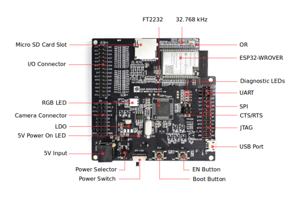
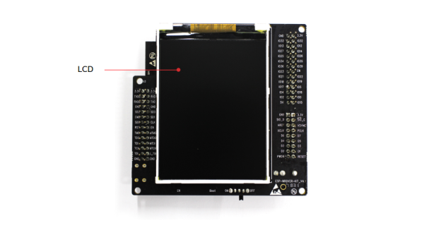
The board is powered via USB cable from the PC computer (micro USB).
This board integrates debugger (internally via JTAG) exposed to the PC as second COM (Serial) port
When you connect the board to the PC you will find two COM/Serial ports present in your system:
- one is for programming the device and monitoring it via Serial Monitor,
- the second one is for debugging.
Mind there is a number of jumpers required to let your board work correct in a particular environment like this laboratory's one, so be careful not to change it.
In case you struggle to make your board working, please check carefully configuration of the jumpers, as presented below.
In case you struggle to make your board working, please check carefully configuration of the jumpers, as presented below.
| Problem | Jumper/Header | Description |
|---|---|---|
| Development board won't power on even when the master power switch is on. | JP7 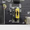 3) | This header enables you to power development board from the external, barrel connector. It is useful when you need to deliver more power to the board than USB can handle but not a case in our laboratory, so keep it short with USB enabled on, as on the image. When your board won't wake up, check this first. |
| Debugger is not working via 2nd COM port. | JP2 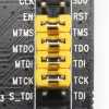 4) | This header redirects debugger into the COM-to-USB bridge. Keep those 4 jumpers short, unless you use external, JTAG, hardware debugger. Otherwise, you won't be able to use the debug feature. |
| Cannot program nor monitor the board via USB. | JP2 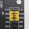 5) | This header enables COM-to-USB communication to the PC. Keep those 2 jumpers short any time, otherwise, you won't be able to program it nor use the serial monitor to observe results. |
Sensors
This development board does not contain any environmental sensors so there is a 37 pcs sensor set that can be used when connected to the GPIOs of the development board, using F-F 2.54 cables. ESP32 exposes a number of GPIOs. Not all of them are “general purpose” - some are dedicated to handling analogue inputs while some others are dedicated to implementing communication protocols like I2C, SPI, software serial and so on. As this development board has some features like i.e. RGB LED and LCD display, many of the GPIOs are already used and even if exposes on the header, should not be used to connect sensors, i.e., if you connect a sensor to the LED dedicated GPIOs, LED, may disturb communication protocol and at least will flash when communication occurs. Opposite, your LCD display may not work correctly, if you connect a sensor to the GPIOs operating the LCD. A good practice is to use those GPIO lines that are not in use with the hardware integrated into the development board.
Some of the GPIOs are dedicated to implementing a limited number of features while on this development board, some of them are dedicated to using a particular protocol. As this development board contains some peripherals (RGB LED, LCD display) do not use GPIOs that are controlling them.
Following list present GPIOs used with the integrated hardware:
| No | Feature | ESP32 GPIO Pin | Notes |
|---|---|---|---|
| 1 | JTAG | GPIO12-15 | |
| 2 | Camera | GPIO0, GPIO4-5, GPIO18-19, GPIO21-23, GPIO25-27, GPIO34-36, GPIO39 | If you do not use the camera, feel free to use those GPIOs unless they're not shared with another feature. |
| 3 | RGB LED | GPIO0, GPIO2, GPIO4 | |
| 4 | MicroSD card reader | GPIO2, GPIO4, GPIO12-15, GPIO21 | |
| 5 | LCD | GPIO5, GPIO18-19, GPIO21-23, GPIO25 |
DHT11
This is the temperature and humidity sensor, delivering calibrated (yet not very accurate) data in Celsius and % of the relative humidity of the air. This sensor uses a single data line, so by the power (GND, VCC 5V/3.3V), it requires single GPIO to operate.
Touch sensor
This sensor uses a switch button so it simply shorts connection of the GPIO line, binary way. By the power, it requires single GPIO to operate.
Actuators
Built-in integrated LCD (TFT) display
The built-in display is ILI9341 TFT display, 320×240 pixels (240×320 actually), RGB, 262k colours. Although it is possible to program it raw, we will use a ready software library to control it.
RGB LED
RGB led is composed of the three independent LEDs: red, green and blue, controlled via separate GPIOs. You can control the brightness of each LED (RGB component) via PWM.
Note it is different from the popular WS2812 LED chains, where each led is controlled digitally, using single GPIO and complex protocol and each LED has dedicated microcontroller.
A special notes on PWM in ESP32
PWM is frequently used to control analogue-style, efficient voltage on the GPIO pin. Instead of using resistance driver, PWM uses pulses to change effective power, delivered to the actuator. It applies to motors, but also to LEDs, bulbs, heaters and indirectly to the servos (but that works actually another way, see lectures).
Classical analogWrite method as known from Arduino (Uno, Mega) and ESP8266 does not work here.
ESP32 has sixteen (0 to 15) PWM channels (controllers) that can be freely bound to any of the regular GPIOs.
ESP32 can use various “resolutions” of the PWM: from 8 bit (0..255) to 15bit (0..32767) while regular Arduino uses only 8 bit one.
To use PWM in ESP32 one must perform the following steps:
- Configure GPIO pin as
OUTPUT - Initiate PWM controller with fixing PWM frequency and resolution
- Bind controller to the GPIO pin
- Write to the controller (not to the PIN!) providing duty cycle related to the resolution selected above - every call persistently sets PWM duty cycle until there is the next call to the function setting duty cycle.
Software
For the laboratory works, a good choice is to use Visual Studio Code with PlatformIO extension.
PlatformIO is installed as an extension from under Visual Studio Code, NOT via external download and manual install.
Under PlatformIO one need to install ESP32 platform (development framework) that comes with the ability to create and implement projects using Arduino-style and IDF-style. Following scenarios assume one uses Arduino-style source code design and platform, even, if we do develop for ESP32, not Arduino.
There is a need to install a number of libraries that will simplify work with external devices (sensors, actuators) but this varies among laboratory scenarios, so refer to the particular scenario for a list of required libraries.
Visual Studio Code offers integrated debugger that can be used directly (without extra JTAG hardware interface) with ESP32 WROVER DEV board, using second COM port.
Laboratory scenarios
Lab 1 - Hello World!
The purpose of this laboratory is to configure your development environment, connect hardware and compile the first “Hello World” application.
You will use a serial port to trace and send your first Hello World message to the computer, then write it on the LCD screen.
Libraries
Serial port tools are embedded into the ESP32 development framework, so SPI protocol implementation is. But to use an integrated LCD display, you need to install the following extra libraries:
- Adafruit GFX Library by Adafruit - for graphical operations,
- WROVER KIT LCD by Adafruit - for handling communication with the display.
It is also pretty common to include Arduino.h to let you use GPIO ids as in case of Arduino Uno in your main.cpp source code file:
...
#include <Arduino.h>
...
Task 1 - using the serial port to send periodically Hello World to your PC via COM port
Serial port communication is very useful to trace (not DEBUG!) actions taken in your implementation. Here is, how to start:
- In a
setup()section of the code, start your serial communication providing speed (usually 9600 or 115200 but virtually any common serial port communication speed is OK here, but please note, you need o change it accordingly in VS Code Serial Monitor tool: default is 9600 so we suggest to use it). - Whenever you want to send something to the console, use
printorprintlnfunctions. - As serial port is bidirectional one, you can also “read” input from the serial stream but we won't use this feature in this scenario.
To delay execution of the code, you can safely call
delay(x) where x is a time in milliseconds to temporary stop execution of your code. It is useful in case of the loop() function to let you be able to observe results.
Use the following code (excerpt) in your main.cpp to start serial communication on 9600 bps:
...
void setup() {
...
   Serial.begin(9600);
...
}
...
and then in the loop section:
...
void loop() {
...
   Serial.println("Hello world");
...
   delay(2000);
...
}
Task 2 - counter
Add a counter to your loop, to present a number of times the loop has been executed, modulo 255.
Print this number to the serial port.
The desired result is: numbers from 0 to 255 should appear one number per line.
Adapt delay to speed it up!
Task 3 - controlling LEDs
Using a counter implemented as above, you will control RED (GREEN or BLUE) LED with PWM signal to change its brightness. Within the loop, use a counter to change the duty cycle from 0 to 100% (from 0 to 255 on 8-bit resolution). Use a 5kHz PWM signal.
This algorithm will increase the brightness of the LED from dark towards brighter and then back starts from 0.
Consider using the following configuration in your setup function:
...
#define REDLED 0
...
const int freq = 5000;
const int ledChannel = 0;
const int resolution = 8;
...
void setup() {
...
  pinMode(REDLED, OUTPUT);
...
  ledcSetup(ledChannel, freq, resolution);
  ledcAttachPin(REDLED,ledChannel);
...
and then to set PWM duty cycle, you may use:
...
  ledcWrite(ledChannel, dutycyclevalue);
  delay(15);
...
Task 4 - controlling LEDs #2
Now modify code above to use three controllers (one per LED) and provide a solution to pulse LEDs, one colour at a time:
RED from 0 to 255 and back to 0 then GREEN (0..255..0) and then BLUE and loop back to RED and so on.
Task 5 - write Hello World on the LCD screen.
Now, type textual “Hello World” on the screen. You're welcome to decorate it, change colours, size, orientation, etc.
To use LCD you must include libraries. Beginning of your main.cpp should then look more-less following way:
...
#include "SPI.h"
#include "Adafruit_GFX.h"
#include "WROVER_KIT_LCD.h"
...
Then define a controller class that manages your LCD:
...
WROVER_KIT_LCD tft;
...
A number of useful functions to handle LCD operations is presented below (but not limited to):
...
  tft.fillScreen(WROVER_BLACK); //Clear screen
  tft.setCursor(0, 0); //Set upper left corner
  tft.setTextColor(WROVER_WHITE);  //Set text colour
  tft.setTextSize(1); //Set font size
  tft.println("Hello World!"); // Print the text
...
Resources
On-line course
Join this course on-line (you need to register a free account to participate in the course)
IoT course for Bachelor students
en/edu/zmitac/macro/iot/labesp32.1583917251.txt.gz · Last modified: by pczekalski