
No ACL setup yet! Denying access to everyone.
en:edu:zmitac:s2:iot:aih
This is an old revision of the document!
Table of Contents
Laboratory on the Internet of Things - Advanced IoT Hardware
Laboratory guide for IoT AIH students on ESP32 programming, using VREL distance labs and two types of ESP32 modules:
- ESP32 WROVER DEVKIT module - that includes (among others) dot-matrix LCD TFT display
- TTGO T5 v 2.2 module - that contains a 2.9 Waveshare e-paper, two-colour display
You can access the distant laboratory (VREL) interface here: http://distance.roboticlab.eu/.
You need to register an account (unless you have one, already). A short video presenting the account creation process and first steps is here: https://youtu.be/0R6oUWkBrpQ
Hardware
You will use laboratory nodes #25 and #20:
- TTGO with e-Paper module is VREL node #25
- WROVER DEVKIT with LCD TFT module is VREL node #20
Below we present hardware details on the two modules:
ESP32 WROVER DEVKIT
This board is double-sided, on one side you will find an LCD screen (so-called back) on the other side (front) there are GPIOs connectors you connect sensors and actuators to, TF (microSD) card slot with SPI reader and an RGB LED diode (among others).
Please note you can directly observe only the back side of the module via VREL node's camera.
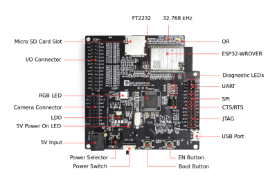
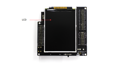
ESP32 provides a number of GPIOs to the developers, but some of them are hard-bound to their features as connected on the development board.
Some of the GPIOs are dedicated to implementing a limited number of features while on this development board, some of them are dedicated to using a particular protocol. As this development board contains some peripherals (RGB LED, LCD display, TF card reader) do not use GPIOs that are controlling them.
Following list present GPIOs used with the integrated hardware:
Tab. 1: ESP32 WROVER DEVKIT GPIO and features
| No | Feature | ESP32 GPIO Pin | Notes |
|---|---|---|---|
| 1 | JTAG | GPIO12-15 | |
| 2 | Camera | GPIO0, GPIO4-5, GPIO18-19, GPIO21-23, GPIO25-27, GPIO34-36, GPIO39 | If you do not use the camera, feel free to use those GPIOs unless they're not shared with another feature. |
| 3 | RGB LED | GPIO0, GPIO2, GPIO4 | |
| 4 | MicroSD card reader | GPIO2, GPIO4, GPIO12-15, GPIO21 | |
| 5 | LCD | GPIO5, GPIO18-19, GPIO21-23, GPIO25 |
Note - GPIOs 34, 35, 36 and 39 do not have internal pull-up nor pull-down resistors
Built-in integrated LCD (TFT) display
The built-in display is ILI9341 TFT display, 320×240 pixels (240×320 actually), RGB, 262k colours. Although it is possible to program it raw, we will use a ready software library to control it. This TFT display uses 16-bit per pixel memory organisation, frequently referenced as 565 (RGB, R-5-bits, G-6-bits, B-5-bits).
Configuring VREL - platformio.ini
Correct configuration is necessary to build and deploy your code.
For ESP32 WROVER DEVKIT, a good starting point is the following content for platformio.ini file:
[env:d1_mini]
platform = espressif32
board = esp-wrover-kit
framework = arduino
upload_port = /dev/ttyUSB1
lib_deps =
	adafruit/Adafruit-GFX-Library
	Wire
 	espressif/WROVER_KIT_LCD
Practice: handling LCD display
Write Hello World on the LCD screen.
Using LCD display and a camera, you can observe it through, are your only interface to the devkit. Get familiar with handling LCD screen and give it a short practice, as present below.
Type textual “Hello World” on the screen. You're welcome to decorate it, change colours, size, orientation, etc.
To use LCD you must include libraries. Beginning of your .cpp source code file should then look more-less following way:
...
#include <Arduino.h>
#include <SPI.h>
#include <Adafruit_GFX.h>
#include <Adafruit_I2CDevice.h>
#include <WROVER_KIT_LCD.h>
...
Then define a controller class that manages your LCD:
...
WROVER_KIT_LCD tft;
...
Some useful functions to handle LCD operations are presented below (but not limited to):
...
  tft.fillScreen(WROVER_BLACK); //Clear screen
  tft.setCursor(0, 0); //Set upper left corner
  tft.setTextColor(WROVER_WHITE);  //Set text colour
  tft.setTextSize(1); //Set font size
  tft.println("Hello World!"); // Print the text
...
TTGO T5 v.2.2 e-Paper
TTGO (aka LILYGO) ESP32 module with integrated e-Paper 2.9-inch display is a robust solution for e-Paper development. Here you will learn basics on handling the e-Paper (e-Ink). The display is two coloured (black/white) with 296×128 pixels resolution. The display is connected and operated via SPI bus
The TTGO T5 module also contains a speaker (buzzer), SPI TF card reader, and a limited GPIO. It is advertised as an electronic badge.


ESP32 provides a number of GPIOs to the developers, but some of them are hard-bound to their features as connected on the development board.
Some of the GPIOs are dedicated to implementing a limited number of features while on this development board, some of them are dedicated to using a particular protocol. As this development board contains some peripherals (RGB LED, LCD display, TF card reader) do not use GPIOs that are controlling them.
Tab. 2: TTGO T5 v2.2 GPIO and features
| No | Feature | ESP32 GPIO Pin | Notes |
|---|---|---|---|
| 1 | e-Paper SPI interface | GPIO4, GPIO12, GPIO19, GPIO5, GPIO23, GPIO18 | In order: EPaper BUSY, ePaper RST, EPaper DC, EPaper CS, EPaper MOSI, EPaper SCLK |
| 2 | MicroSD card reader | GPIO13, GPIO23, GPIO2, GPIO18 | In order: SDCard CS, SDCard MOSI, SDCard MISO, SDCard SCLK |
| 3 | Buttons | GPIO37, GPIO38, GPIO39 | In order buttons 1,2,3 |
| 4 | Speaker | GPIO25 | Channel 0 |
Built-in integrated e-Paper display
The e-Paper (e-Ink) display is a bi-coloured, 296×128 pixels with SPI interface module, manufactured by Waveshare. It has an integrated SPI controller 3).
There are various software libraries able to handle e-Paper displays but the most advanced one at the moment is GxEPD library that includes device drivers for the majority of manufactured displays Github GxEPD library. The exact model (as to be included in the code is GDEH029A1 https://github.com/lewisxhe/GxEPD/tree/master/src/GxGDEH029A1.
Configuring VREL - platformio.ini
Correct configuration is necessary to build and deploy your code.
For ESP32 TTGO T5 v2.2, a good starting point is the following content for platformio.ini file:
[env:d1_mini]
platform = espressif32
board = esp-wrover-kit
framework = arduino
lib_deps =
	adafruit/Adafruit-GFX-Library
	Wire
	zinggjm/GxEPD
Practice: handling e-Paper display
Write Hello World on the e-Paper screen.
Using e-Paper display and a camera, you can observe it through, are your only interface to the TTGO. Get familiar with handling e-Paper and give it a short practice, as present below.
Type textual “Hello World” on the screen. You're welcome to decorate it, change the size, orientation, experiment with bitmap displaying, partial updates and so on.
To use e-Paper you must include libraries. Beginning of your .cpp source code file should then look more-less following way:
...
#include <Arduino.h>
#include <GxEPD.h>
#include <Adafruit_I2CDevice.h>
#include "SPI.h"
#include <GxIO/GxIO_SPI/GxIO_SPI.h>
#include <GxIO/GxIO.h>

//TTGO e-Ink T5 EP32 v 2.2. board specific:
#include <GxGDEH029A1/GxGDEH029A1.h> // 2.9" b/w
#define ELINK_BUSY 4
#define ELINK_RESET 12
#define ELINK_DC 19
#define ELINK_SS 5

#define SPI_MOSI 23
#define SPI_MISO 2
#define SPI_CLK 18
...
Note, by the e-Paper related display drivers there is also a font definition library should be included:
...
#include <Fonts/FreeSans9pt7b.h>
...
and then define this font as a default one to use code below:
...
#define DEFALUT_FONT FreeSans9pt7b
...
Then define a controller class that manages your e-Ink display:
...
GxIO_Class io(SPI, ELINK_SS, ELINK_DC, ELINK_RESET);
GxEPD_Class display(io, ELINK_RESET, ELINK_BUSY);
...
Some useful functions to handle e-Paper operations are presented below (but not limited to):
...
  SPI.begin(SPI_CLK, SPI_MISO, SPI_MOSI, -1);
  display.init();
  display.setRotation(1);
  display.eraseDisplay();
  display.setTextColor(GxEPD_BLACK);
  display.setFont(&DEFALUT_FONT);
  display.setTextSize(0);

  display.fillScreen(GxEPD_WHITE);
  display.setCursor(20,20);
  display.println("Hello world");
  display.update();
...
Note, for ease, there are predefined values that present black and white colour display: GxEPD_WHITE and GxEPD_BLACK.
You need to use a font to draw on the e-Ink screen. Use one of the definitions provided along with GxEPD library.
In the laboratory node #25, the e-ink display has been mounted landscape. It means, to keep text horizontal, you need to use:
display.setRotation(1);
A special notes on PWM in ESP32
PWM is frequently used to control analogue-style, efficient voltage on the GPIO pin. Instead of using resistance driver, PWM uses pulses to change effective power, delivered to the actuator. It applies to motors, but also to LEDs, bulbs, heaters and indirectly to the servos (but that works actually another way, see lectures).
Classical analogWrite method as known from Arduino (Uno, Mega) and ESP8266 does not work here.
ESP32 has sixteen (0 to 15) PWM channels (controllers) that can be freely bound to any of the regular GPIOs.
ESP32 can use various “resolutions” of the PWM: from 8 bit (0..255) to 15bit (0..32767) while regular Arduino uses only 8 bit one.
To use PWM in ESP32 one must perform the following steps:
- Configure GPIO pin as
OUTPUT - Initiate PWM controller with fixing PWM frequency and resolution
- Bind controller to the GPIO pin
- Write to the controller (not to the PIN!) providing duty cycle related to the resolution selected above - every call persistently sets PWM duty cycle until there is the next call to the function setting duty cycle.
Laboratory scenarios
In general, you will program using the Arduino framework, remotely via a web interface with the use of the VREL system. Note, your only output is to use the web camera, so results are to be presented this way.
You will also use FreeRTOS functions to handle multicore parallel programming to perform tasks, as presented during the lecture.
ESP32 framework uses C++ optimiser while compiling the source code. It is common that C++ traces unused code and removes/optimises it, to minimise CPU effort. As your tasks to be completed involve integer and floating-point performance evaluation it is essential to use the result somewhere, i.e. do a dummy display of the final value on the screen. Otherwise, the C++ compiler may remove this section of the code and you won't be able to obtain reasonable results, because your code may be already trunk and not executed at all!
FreeRTOS, once task is created and scheduled for execution, executes the task infinitely! It means, your function implementing the task will be executed again and again. If you intended to run a looped task, that is pretty OK. If you intended to run one-off task, then you need explicitly call
vTaskDelete(NULL) as a last line of your code!
Task 1
Evaluate single-core performance for integer computation. Perform two experiments: with task bound to the APP core and separately to the PRO core. Observe if there is a difference in measurements. Propose an algorithm that is able to generate a complexity of integer computation observable and measurable. Perform at least 10 measurements for each experiment. Consider using parts of code for Dhrystone benchmark https://en.wikipedia.org/wiki/Dhrystone.
Task 2
Evaluate multi-core performance for integer computation. Perform single-core computation, running at least 4 times (any even number works here) your algorithm. Then execute in parallel (2×2). Observe if there is a difference in measurements. Propose an algorithm that is able to generate a complexity of integer computation observable and measurable. Perform at least 20 measurements for each experiment (10 serial + 10 parallel). Consider using parts of code for Dhrystone benchmark https://en.wikipedia.org/wiki/Dhrystone.
Task 3
Evaluate single-core performance for floating-point computation. Perform two experiments: with task bound to the APP core and separately to the PRO core. Observe if there is a difference in measurements. Propose an algorithm that is able to generate a complex-enough floating points computation that is observable and measurable. Perform at least 10 measurements for each experiment. Consider using FP parts of code for Whetstone benchmark https://en.wikipedia.org/wiki/Whetstone_(benchmark).
Task 4
Evaluate multi-core performance for floating-point computation. Perform single-core computation, running at least 4 times (any even number works here) your algorithm. Then execute in parallel (i.e. 2×2). Propose an algorithm that is able to generate a complex-enough floating point computation that is observable and measurable. Perform at least 20 measurements for each experiment (10 serial + 10 parallel). Consider using FP parts of code for Whetstone benchmark https://en.wikipedia.org/wiki/Whetstone_(benchmark).
Report
Include algorithm definition and measurements, along with statistical analysis of the results (at least average and standard deviation) and a summary.
Resources
en/edu/zmitac/s2/iot/aih.1611044543.txt.gz · Last modified: by pczekalski